Axial-Zylinderrollenlager

Zylinderrollen-Axial-Wäschlager bestehen aus zylindrischen Rollen und einem Käfig-Axial-Wäschsystem sowie zwei Lagerringen. Die Ausführung kann einreihig oder zweireihig sein. Sie sind steif, haben eine hohe Tragfähigkeit und sind stoßfest. Sie können nur Axialkräfte aufnehmen.
Begrenzungsmaße

Die in den Maßtabellen angegebenen Grenzabmessungen für Zylinderrollenlager entsprechen dem internationalen Maßsystem ISO 104.
Entwürfe
Die Komponenten von Zylinderrollen-Axial- oder Axial-Axial-Lagern ermöglichen eine Kombination aus einem Käfig mit Rollen und Laufbahnen, die aus einzelnen Maschinenteilen gebildet werden, oder eine Kombination aus einer Laufbahn, die aus einem Maschinenteil und einem Lagerring gebildet wird. Ein separater Käfig mit Rollen hat die zusätzliche Bezeichnung K, eine separate Wellenscheibe wird mit WS bezeichnet und ein separater Gehäusering wird mit GS bezeichnet.
Bezeichnung
Die Bezeichnung der Lager mit der Grundausführung ist in den Maßtabellen angegeben. Die Abweichung von der Grundausführung wird durch zusätzliche Kennzeichnungen angegeben.
Käfige
Die Käfige der Zylinderrollen-Axial- und Axiallager sind aus Polyamid 66 (Bezeichnung TN) oder Messing (Bezeichnung M) gefertigt.
Präzision
Zylinderrollen-Axial-Wälzlager werden normalerweise mit der normalen Genauigkeitsklasse P0 hergestellt (die Kennzeichnung P0 ist nicht angegeben). Lager mit höheren Genauigkeitsklassen P6 und P5 sind für Sonderanfertigungen erhältlich, die eine höhere Genauigkeit erfordern. Grenzwerte für Abweichungen der Maßgenauigkeit und Laufgenauigkeit sind in ISO 199 angegeben.
Mindest-Axialbelastung
Zylinderrollen-Axial-Wälzlager müssen einer bestimmten Mindestlast ausgesetzt werden, um eine zuverlässige Lagerfunktion zu gewährleisten. Wird diese Last nicht eingehalten, kann es zu abnormalem Abrollen und Rutschen der Wälzkörper und damit zu Schäden an den Laufbahnen kommen.
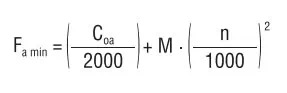
Die Mindestlast wird wie folgt berechnet:
Wo
Fa min – minimale Axialbelastung [kN]
C0a – statische Belastbarkeit [kN]
n – Drehzahl [min-1]
M – Koeffizient der minimalen Axialbelastung
(Die Werte sind in den Maßtabellen angegeben.)
Sofern die Mindestbelastung nicht auf natürliche Weise in der Lageranordnung entsteht, muss das Lager durch eine Wellenmutter oder Federn mit einer zusätzlichen Kraft belastet werden.
Axiale dynamische und statische Ersatzbelastung
Axial Equivalent Dynamic Load
Pa = Fa
Axial Equivalent Static Load
Poa = Fa
Produktfilter:
| Lagerbezeichnung | Abmessungen | Tragzahl | Ermüdungsgrenz - belastung | Minimaler axialer Belastungsfaktor | Grenzdrehzahlen für die Schmierung mit | Gewicht | Bezeichnung der Lagerbestandteile | |||||||||||||
|---|---|---|---|---|---|---|---|---|---|---|---|---|---|---|---|---|---|---|---|---|
| dynamische | statische | |||||||||||||||||||
| d Dc1 | D1 | Dc D | d1 | H | Dw | B | rsmin | Eb | Ea | Cr | Cor | Cu | M | Fett | Öl | Käfig mit Zylinder | Wellenring | Körperring | ||
| mm | kN | min-1 | kg | |||||||||||||||||
| 81102TN | 15 | 16 | 28 | 28 | 9 | 3.5 | 2.75 | 0.3 | 16 | 27 | 11.7 | 24.0 | 2.9 | 0.00006 | 13 600 | 6 300 | 0.024 | K81102TN | WS 81102 | GS 81102 |
| 81103TN | 17 | 18 | 30 | 30 | 9 | 3.5 | 2.75 | 0.3 | 18 | 29 | 12.9 | 28.4 | 3.4 | 0.00008 | 12 400 | 5 400 | 0.027 | K81103TN | WS 81103 | GS 81103 |
| 81104TN | 20 | 21 | 35 | 35 | 10 | 4.5 | 2.75 | 0.3 | 21 | 34 | 18.7 | 39.8 | 4.8 | 0.00019 | 10 500 | 4 300 | 0.037 | K81104TN | WS 81104 | GS 81104 |
| 81105TN | 25 | 26 | 42 | 42 | 11 | 5 | 3 | 0.6 | 26 | 41 | 25.2 | 59.0 | 7.2 | 0.0004 | 8 600 | 3 500 | 0.053 | K81105TN | WS 81105 | GS 81105 |
| 81106TN | 30 | 32 | 47 | 47 | 11 | 5 | 3 | 0.6 | 31 | 46 | 26.8 | 68.3 | 8.3 | 0.0005 | 7 500 | 3 050 | 0.057 | K81106TN | WS 81106 | GS 81106 |
| 81206TN | 30 | 32 | 52 | 52 | 16 | 7.5 | 4.25 | 0.6 | 31 | 50 | 49.5 | 108.4 | 13.2 | 0.0014 | 7 100 | 2 650 | 0.123 | K81206TN | WS 81206 | GS 81206 |
| 89306TN | 30 | 32 | 60 | 60 | 18 | 5.5 | 6.25 | 1 | 33 | 59 | 52.4 | 159.7 | 19.5 | 0.003 | 6 400 | 2 600 | 0.240 | K89306TN | WS 89306 | GS 89306 |
| 81107TN | 35 | 37 | 52 | 52 | 12 | 5 | 3.5 | 0.6 | 36 | 51 | 29.4 | 81.8 | 10.0 | 0.0007 | 6 600 | 2 600 | 0.073 | K81107TN | WS 81107 | GS 81107 |
| 81207TN | 35 | 37 | 62 | 62 | 18 | 7.5 | 5.25 | 1 | 39 | 58 | 50.7 | 121.5 | 14.8 | 0.003 | 5 900 | 2 320 | 0.195 | K81207TN | WS 81207 | GS 81207 |
| 89307TN | 35 | 37 | 68 | 68 | 20 | 6 | 7 | 1 | 38 | 67 | 61.5 | 194.0 | 23.6 | 0.004 | 5 600 | 2 390 | 0.340 | K89307TN | WS 89307 | GS 89307 |
| 81108TN | 40 | 42 | 60 | 60 | 13 | 6 | 3.5 | 0.6 | 42 | 58 | 42.7 | 120.8 | 14.7 | 0.0016 | 5 800 | 2 190 | 0.105 | K81108TN | WS 81108 | GS 81108 |
| 81208TN | 40 | 42 | 68 | 68 | 19 | 9 | 5 | 1 | 43 | 66 | 84.1 | 211.2 | 25.7 | 0.0053 | 5 200 | 1 860 | 0.249 | K81208TN | WS 81208 | GS 81208 |
| 89308TN | 40 | 42 | 78 | 78 | 22 | 7 | 7.5 | 1 | 44 | 77 | 79.6 | 252.4 | 30.8 | 0.011 | 4 800 | 1 780 | 0.484 | K89308TN | WS 89308 | GS 89308 |
| 81109TN | 45 | 47 | 65 | 65 | 14 | 6 | 4 | 0.6 | 47 | 63 | 44.9 | 134.5 | 16.4 | 0.002 | 5 300 | 1 970 | 0.130 | K81109TN | WS 81109 | GS 81109 |
| 81209TN | 45 | 47 | 73 | 73 | 20 | 9 | 5.5 | 1 | 48 | 70 | 82.4 | 214.8 | 26.2 | 0.0059 | 4 850 | 1 820 | 0.287 | K81209TN | WS 81209 | GS 81209 |
| 89309TN | 45 | 47 | 85 | 85 | 24 | 7.5 | 8.25 | 1 | 49 | 83 | 107.9 | 371.6 | 45.3 | 0.015 | 4 400 | 1 620 | 0.615 | K89309TN | WS 89309 | GS 89309 |
| 81110TN | 50 | 52 | 70 | 70 | 14 | 6 | 4 | 0.6 | 52 | 68 | 47.0 | 148.3 | 18.8 | 0.0023 | 4 800 | 1 810 | 0.140 | K81110TN | WS 81110 | GS 81110 |
| 81210TN | 50 | 52 | 78 | 78 | 22 | 9 | 6.5 | 1 | 53 | 75 | 81.0 | 217.8 | 26.5 | 0.0072 | 4 450 | 1 550 | 0.356 | K81210TN | WS 81210 | GS 81210 |
| 89310TN | 50 | 52 | 95 | 95 | 27 | 8 | 9.5 | 1.1 | 56 | 92 | 130.8 | 473.5 | 57.7 | 0.023 | 3 950 | 1 460 | 0.887 | K89310TN | WS 89310 | GS 89310 |
| 81111TN | 55 | 57 | 78 | 78 | 16 | 6 | 5 | 0.6 | 57 | 77 | 70.0 | 259.4 | 31.6 | 0.0068 | 4 300 | 1 330 | 0.218 | K81111TN | WS 81111 | GS 81111 |
| 81211TN | 55 | 57 | 90 | 90 | 25 | 11 | 7 | 1 | 59 | 85 | 110.0 | 287.4 | 35.0 | 0.013 | 4 000 | 1 510 | 0.568 | K81211TN | WS 81211 | GS 81211 |
| 89311TN | 55 | 57 | 105 | 105 | 30 | 9 | 10.5 | 1.1 | 61 | 103 | 151.1 | 537.7 | 65.6 | 0.026 | 3 600 | 1 490 | 1.180 | K89311TN | WS 89311 | GS 89311 |
| 81112TN | 60 | 62 | 85 | 85 | 17 | 7.5 | 4.75 | 1 | 62 | 82 | 80.1 | 267.6 | 32.6 | 0.0075 | 4 000 | 1 360 | 0.266 | K81112TN | WS 81112 | GS 81112 |
| 81212TN | 60 | 62 | 95 | 95 | 26 | 11 | 7.5 | 1 | 64 | 91 | 136.2 | 394.5 | 48.1 | 0.018 | 3 700 | 1 300 | 0.642 | K81212TN | WS 81212 | GS 81212 |
| 89312TN | 60 | 62 | 110 | 110 | 30 | 9 | 10.5 | 1.1 | 66 | 108 | 154.0 | 566.5 | 69.1 | 0.033 | 3 350 | 1 350 | 1.260 | K89312TN | WS 89312 | GS 89312 |
| 89412TN | 60 | 62 | 130 | 130 | 42 | 14 | 14 | 1.5 | 65 | 126 | 309.3 | 1008.4 | 123.0 | 0.111 | 3 000 | 1 080 | 2.818 | K89412TN | WS 89412 | GS 89412 |
| 81113TN | 65 | 67 | 90 | 90 | 18 | 7.5 | 5.25 | 1 | 67 | 87 | 83.4 | 289.6 | 35.3 | 0.0083 | 3 700 | 1 260 | 0.310 | K81113TN | WS 81113 | GS 81113 |
| 81213TN | 65 | 67 | 100 | 100 | 27 | 11 | 8 | 1 | 69 | 96 | 139.4 | 419.5 | 51.1 | 0.020 | 3 450 | 1 240 | 0.721 | K81213TN | WS 81213 | GS 81213 |
| 89313TN | 65 | 67 | 115 | 115 | 30 | 9 | 10.5 | 1.1 | 71 | 113 | 152.1 | 570.2 | 69.5 | 0.033 | 3 200 | 1 330 | 1.330 | K89313TN | WS 89313 | GS 89313 |
| 89413TN | 65 | 68 | 140 | 140 | 45 | 15 | 15 | 2 | 70 | 135 | 352.6 | 1166.3 | 141.2 | 0.150 | 2 800 | 1 000 | 3.520 | K89413TN | WS 89413 | GS 89413 |
| 81114TN | 70 | 72 | 95 | 95 | 18 | 7.5 | 5.25 | 1 | 72 | 92 | 86.4 | 311.6 | 38.0 | 0.0096 | 3 500 | 1 170 | 0.33 | K81114TN | WS 81114 | GS 81114 |
| 81214TN | 70 | 72 | 105 | 105 | 27 | 11 | 8 | 1 | 74 | 102 | 148.0 | 465.5 | 56.7 | 0.023 | 3 250 | 1 130 | 0.77 | K81214TN | WS 81214 | GS 81214 |
| 89314TN | 70 | 72 | 125 | 125 | 34 | 10 | 12 | 1.1 | 76 | 123 | 99.9 | 315.9 | 38.5 | 0.050 | 2 950 | 1 200 | 1.82 | K89314TN | WS 89314 | GS 89314 |
| 89414TN | 70 | 73 | 150 | 150 | 48 | 16 | 16 | 2 | 76 | 147 | 378.5 | 1246.5 | 147.7 | 0.171 | 2 650 | 1 000 | 4.18 | K89414TN | WS 89414 | GS 89414 |
| 81115TN | 75 | 77 | 100 | 100 | 19 | 7.5 | 5.75 | 1 | 78 | 97 | 83.3 | 303.2 | 37.0 | 0.009 | 3 300 | 1 190 | 0.40 | K81115TN | WS 81115 | GS 81115 |
| 81215TN | 75 | 77 | 110 | 110 | 27 | 11 | 8 | 1 | 79 | 106 | 135.8 | 426.4 | 52.0 | 0.019 | 3 100 | 1 210 | 0.80 | K81215TN | WS 81215 | GS 81215 |
| 89315TN | 75 | 77 | 135 | 135 | 36 | 11 | 12.5 | 1.5 | 81 | 132 | 226.8 | 866.6 | 104.1 | 0.075 | 2 750 | 1 080 | 2.23 | K89315TN | WS 89315 | GS 89315 |
| 89415M | 75 | 78 | 160 | 160 | 51 | 17 | 17 | 2 | 82 | 153 | 398.1 | 1297.5 | 150.7 | 0.187 | 2 400 | 1 000 | 5.96 | K89415M | WS 89415 | GS 89415 |
| 81116TN | 80 | 82 | 105 | 105 | 19 | 7.5 | 5.75 | 1 | 83 | 102 | 82.2 | 304.8 | 37.1 | 0.009 | 3 100 | 1 170 | 0.40 | K81116TN | WS 81116 | GS 81116 |
| 81216TN | 80 | 82 | 115 | 115 | 28 | 11 | 8.5 | 1 | 84 | 112 | 158.7 | 536.7 | 65.4 | 0.029 | 2 900 | 990 | 0.90 | K81216TN | WS 81216 | GS 81216 |
| 89316TN | 80 | 82 | 140 | 140 | 36 | 11 | 12.5 | 1.5 | 86 | 137 | 241.0 | 958.3 | 113.6 | 0.090 | 2 600 | 990 | 2.37 | K89316TN | WS 89316 | GS 89316 |
| 89416M | 80 | 83 | 170 | 170 | 54 | 18 | 18 | 2.1 | 88 | 165 | 443.6 | 1463.0 | 166. | 0.239 | 2 260 | 950 | 7.40 | K89416M | WS 89416 | GS 89416 |
| 81117TN | 85 | 87 | 110 | 110 | 19 | 7.5 | 5.75 | 1 | 87 | 108 | 87.3 | 336.8 | 41.0 | 0.012 | 2 950 | 1 070 | 0.42 | K81117TN | WS 81117 | GS 81117 |
| 81217TN | 85 | 88 | 125 | 125 | 31 | 12 | 9.5 | 1 | 90 | 119 | 170.9 | 565.9 | 68.0 | 0.025 | 2 750 | 1 060 | 1.26 | K81217TN | WS 81217 | GS 81217 |
| 89317M | 85 | 88 | 150 | 150 | 39 | 12 | 13.5 | 1.5 | 93 | 147 | 256.5 | 990.8 | 115.1 | 0.097 | 2 400 | 1 030 | 3.39 | K89317M | WS89317 | GS 89317 |
| 89417M | 85 | 88 | 180 | 180 | 58 | 19 | 19.5 | 2.1 | 93 | 175 | 491.2 | 1638.5 | 183.6 | 0.298 | 2 130 | 900 | 8.65 | K89417M | WS 89417 | GS 89417 |
| 81118TN | 90 | 92 | 120 | 120 | 22 | 9 | 6.5 | 1 | 93 | 117 | 110.4 | 405.5 | 48.7 | 0.014 | 2 750 | 1 070 | 0.62 | K81118TN | WS 81118 | GS 81118 |
| 81218TN | 90 | 93 | 135 | 135 | 35 | 14 | 10.5 | 1.1 | 95 | 129 | 231.5 | 759.4 | 89.4 | 0.061 | 2 550 | 910 | 1.77 | K81218TN | WS 81218 | GS 81218 |
| 89318M | 90 | 93 | 155 | 155 | 39 | 12 | 13.5 | 1.5 | 98 | 152 | 264.1 | 1047.8 | 120.2 | 0.108 | 2 310 | 980 | 3.63 | K89318M | WS 89318 | GS 89318 |
| 89418M | 90 | 93 | 190 | 190 | 60 | 20 | 20 | 2.1 | 99 | 185 | 541.8 | 1823.9 | 201.0 | 0.360 | 2 010 | 850 | 9.94 | K89418M | WS 89418 | GS 89418 |
| 81120TN | 100 | 102 | 135 | 135 | 25 | 11 | 7 | 1 | 104 | 131 | 157.2 | 570.3 | 66.2 | 0.028 | 2 460 | 920 | 0.95 | K81120TN | WS 81120 | GS 81120 |
| 81220TN | 100 | 103 | 150 | 150 | 38 | 15 | 11.5 | 1.1 | 107 | 142 | 271.4 | 921.7 | 105.1 | 0.056 | 2 300 | 840 | 2.20 | K81220TN | WS 81220 | GS 81220 |
| 89320M | 100 | 103 | 170 | 170 | 42 | 13 | 14.5 | 1.5 | 107 | 167 | 302.6 | 1219.9 | 135.9 | 0.150 | 2 090 | 910 | 4.56 | K89320M | WS 89320 | GS 89320 |
| 89420M | 100 | 103 | 210 | 210 | 67 | 22 | 22.5 | 3 | 111 | 205 | 680.7 | 2372.2 | 253.6 | 0.627 | 1 810 | 720 | 13.4 | K89420M | WS 89420 | GS 89420 |
| 81122TN | 110 | 112 | 145 | 145 | 25 | 11 | 7 | 1 | 114 | 141 | 162.9 | 619.1 | 70.2 | 0.031 | 2 260 | 850 | 1.40 | K81122TN | WS 81122 | GS 81122 |
| 81222TN | 110 | 113 | 160 | 160 | 38 | 15 | 11.5 | 1.1 | 117 | 152 | 257.4 | 890.6 | 99.2 | 0.068 | 2 130 | 860 | 2.29 | K81222TN | WS 81222 | GS 81222 |
| 89322M | 110 | 113 | 190 | 190 | 48 | 15 | 16.5 | 2 | 120 | 186 | 402.2 | 1639.5 | 177.0 | 0.270 | 1 890 | 790 | 6.70 | K89322M | WS 89322 | GS 89322 |
| 89422M | 110 | 113 | 230 | 30 | 73 | 24 | 24.5 | 3 | 121 | 223 | 802.5 | 2844.1 | 295.8 | 0.898 | 1 660 | 640 | 17.4 | K89422M | WS 89422 | GS 89422 |
| 81124TN | 120 | 122 | 155 | 155 | 25 | 11 | 7 | 1 | 124 | 151 | 168.8 | 667.9 | 74.0 | 0.038 | 2 100 | 780 | 1.12 | K81124TN | WS 81124 | GS 81124 |
| 81224TN | 120 | 123 | 170 | 170 | 39 | 15 | 12 | 1.1 | 127 | 162 | 253.6 | 898.2 | 98.0 | 0.076 | 1 990 | 790 | 2.54 | K81224TN | WS 81224 | GS 81224 |
| 89324M | 120 | 123 | 210 | 210 | 54 | 17 | 18.5 | 2.1 | 130 | 206 | 509.3 | 2093.3 | 219.7 | 0.450 | 1 710 | 690 | 9.44 | K89324M | WS 89324 | GS 89324 |
| 89424M | 120 | 123 | 250 | 250 | 78 | 26 | 26 | 4 | 133 | 243 | 934.7 | 3358.7 | 340.5 | 1.217 | 1 520 | 580 | 21.9 | K89424M | WS 89424 | GS 89424 |
| 81126TN | 130 | 132 | 170 | 170 | 30 | 12 | 9 | 1 | 135 | 165 | 199.6 | 801.5 | 86.5 | 0.049 | 1 930 | 760 | 1.67 | K81126TN | WS 81126 | GS 81126 |
| 81226TN | 130 | 133 | 190 | 187 | 45 | 19 | 13 | 1.5 | 137 | 181 | 379.1 | 1296.6 | 137.3 | 0.170 | 1 800 | 710 | 3.98 | K81226TN | WS 81226 | GS 81226 |
| 89326M | 130 | 134 | 225 | 225 | 58 | 18 | 20 | 2.1 | 141 | 220 | 566.1 | 2362.8 | 242.5 | 0.562 | 1 590 | 650 | 11.2 | K89326M | WS 89326 | GS 89326 |
| 89426M | 130 | 134 | 270 | 270 | 85 | 28 | 28.5 | 4 | 145 | 263 | 1061.7 | 3856.7 | 382.0 | 1.620 | 1 400 | 530 | 27.1 | K89426M | WS 89426 | GS 89426 |
| 81128TN | 140 | 142 | 180 | 178 | 31 | 12 | 9.5 | 1 | 145 | 175 | 186.8 | 752.1 | 79.6 | 0.059 | 1 800 | 710 | 1.90 | K81128TN | WS 81128 | GS 81128 |
| 81228M | 140 | 143 | 200 | 197 | 46 | 19 | 13.5 | 1.5 | 147 | 191 | 360.0 | 1241.6 | 129.1 | 0.162 | 1 700 | 730 | 5.70 | K81228M | WS 81228 | GS 81228 |
| 89328M | 140 | 144 | 240 | 240 | 60 | 19 | 20.5 | 2.1 | 152 | 235 | 649.8 | 2780.9 | 279.7 | 0.769 | 1 490 | 570 | 13.2 | K89328M | WS 89328 | GS 89328 |
| 89428M | 140 | 144 | 280 | 280 | 85 | 28 | 28.5 | 4 | 155 | 273 | 1105.1 | 4164.2 | 406.5 | 1.843 | 1 340 | 490 | 29.8 | K89428M | WS 89428 | GS 89428 |
| 81130TN | 150 | 152 | 190 | 188 | 31 | 12 | 9.5 | 1 | 155 | 185 | 213.6 | 917.7 | 95.4 | 0.067 | 1 700 | 660 | 2.20 | K81130TN | WS 81130 | GS 81130 |
| 81230M | 150 | 153 | 215 | 212 | 50 | 21 | 14.5 | 1.5 | 158 | 211 | 468.7 | 1665.6 | 169.6 | 0.300 | 1 540 | 650 | 7.17 | K81230M | WS 81230 | GS 81230 |
| 89330M | 150 | 154 | 250 | 250 | 60 | 19 | 20.5 | 2.1 | 162 | 245 | 665.2 | 2929.5 | 290.2 | 0.845 | 1 410 | 510 | 13.9 | K89330M | WS 89330 | GS 89330 |
| 89430M | 150 | 154 | 300 | 300 | 90 | 30 | 30 | 4 | 167 | 293 | 1260.7 | 4804.8 | 459.4 | 2.509 | 1 240 | 445 | 35.4 | K89430M | WS 89430 | GS 89430 |
| 81132TN | 160 | 162 | 200 | 198 | 31 | 12 | 9.5 | 1 | 165 | 195 | 215.5 | 948.6 | 97.0 | 0.085 | 1 600 | 670 | 2.12 | K81132TN | WS 81132 | GS 81132 |
| 81232M | 160 | 163 | 225 | 222 | 51 | 21 | 15 | 1.5 | 168 | 220 | 480.5 | 1756.7 | 176.0 | 0.330 | 1 470 | 610 | 7.60 | K81232M | WS 81232 | GS 81232 |
| 89432M | 160 | 164 | 320 | 320 | 95 | 32 | 31.5 | 5 | 179 | 313 | 1425.7 | 5491.2 | 515.0 | 3.300 | 1 160 | 410 | 42.0 | K89432M | WS 89432 | GS 89432 |
| 81134TN | 170 | 172 | 215 | 213 | 34 | 14 | 10 | 1.1 | 176 | 209 | 285.2 | 1242.9 | 124.5 | 0.110 | 1 500 | 570 | 2.41 | K81134TN | WS 81134 | GS 81134 |
| 81234M | 170 | 173 | 240 | 234 | 55 | 22 | 16.5 | 1.5 | 180 | 235 | 540.9 | 2027.2 | 199.3 | 0.430 | 1 370 | 600 | 9.30 | K81234M | WS 81234 | GS 81234 |
| 89434M | 170 | 174 | 340 | 340 | 103 | 34 | 34.5 | 5 | 191 | 233 | 1599.9 | 6223.4 | 573.1 | 4.150 | 1 090 | 375 | 51.9 | K89434M | WS 89434 | GS 89434 |
| 81136M | 180 | 183 | 225 | 222 | 34 | 14 | 10 | 1.1 | 185 | 219 | 266.5 | 1174.3 | 115.9 | 0.130 | 1 420 | 590 | 3.30 | K81136M | WS 81136 | GS 81136 |
| 81236M | 180 | 183 | 250 | 247 | 56 | 22 | 17 | 1.5 | 190 | 245 | 552.5 | 2127.2 | 206.2 | 0.470 | 1 310 | 580 | 9.90 | K81236M | WS 81236 | GS 81236 |
| 89436M | 180 | 184 | Dc D | 360 | 109 | 36 | 36.5 | 5 | 200 | 351 | 1767.0 | 6918.9 | 626.3 | 5.100 | 1 040 | 360 | 60.0 | K89436M | WS 89436 | GS 89436 |
| 81138M | 190 | 193 | 240 | 237 | 37 | 15 | 11 | 1.1 | 197 | 233 | 308.5 | 1355.6 | 131.4 | 0.170 | 1 330 | 570 | 4.74 | K81138M | WS 81138 | GS 81138 |
| 81238M | 190 | 194 | 270 | 267 | 62 | 26 | 18 | 2 | 200 | 265 | 701.9 | 2599.6 | 246.9 | 0.680 | 1 220 | 530 | 12.8 | K81238M | WS 81238 | GS 81238 |
| 89438M | 190 | 195 | 380 | 380 | 115 | 38 | 38.5 | 5 | 214 | 373 | 1958.8 | 7738.0 | 689.2 | 6.500 | 990 | 330 | 72.1 | K89438M | WS 89438 | GS 89438 |
| 81140M | 200 | 203 | 250 | 247 | 37 | 15 | 11 | 1.1 | 206 | 243 | 312.6 | 1402.6 | 134.1 | 0.190 | 1 270 | 530 | 4.95 | K81140M | WS 81140 | GS 81140 |
| 81240M | 200 | 204 | 280 | 277 | 62 | 26 | 18 | 2 | 210 | 275 | 720.8 | 2737.9 | 256.7 | 0.790 | 1 170 | 485 | 14.2 | K81240M | WS 81240 | GS 81240 |
| 89440M | 200 | 205 | 400 | 400 | 122 | 40 | 41 | 5 | 226 | 393 | 2159.7 | 8602.9 | 754.6 | 8.000 | 940 | 315 | 82.6 | K89440M | WS 89440 | GS 89440 |
| 81144M | 220 | 223 | 270 | 267 | 37 | 15 | 11 | 1.1 | 226 | 263 | 333.6 | 1581.8 | 147.4 | 0.240 | 1 170 | 470 | 5.22 | K81144M | WS 81144 | GS 81144 |
| 81244M | 220 | 224 | 300 | 297 | 63 | 26 | 18.5 | 2 | 230 | 296 | 756.5 | 3014.7 | 276.0 | 0.910 | 1 080 | 435 | 15.3 | K81244M | WS 81244 | GS 81244 |
| 89444M | 220 | 225 | 420 | 420 | 122 | 40 | 41 | 6 | 244 | 411 | 2340.5 | 9843.7 | 846.8 | 10.000 | 870 | 270 | 90.1 | K89444M | WS 89444 | GS 89444 |
| 81148M | 240 | 243 | 300 | 297 | 45 | 18 | 13.5 | 1.5 | 248 | 296 | 478.3 | 2270.1 | 205.5 | 0.500 | 1 050 | 440 | 8.45 | K81148M | WS 81148 | GS 81148 |
| 81248M | 240 | 244 | 340 | 335 | 78 | 32 | 23 | 2.1 | 261 | 335 | 1098.7 | 4321.6 | 382.9 | 1.900 | 960 | 395 | 26.2 | K81248M | WS 81248 | GS 81248 |
| 89448M | 240 | 245 | 440 | 440 | 122 | 40 | 41 | 6 | 266 | 433 | 2407.4 | 10510.3 | 887.9 | 12.000 | 830 | 250 | 95.9 | K89448M | WS 89448 | GS 89448 |
| 81152M | 260 | 263 | 320 | 317 | 45 | 18 | 13.5 | 1.5 | 268 | 316 | 488.9 | 2404.6 | 213.0 | 0.560 | 980 | 390 | 9.80 | K81152M | WS 81152 | GS 81152 |
| 81252M | 260 | 264 | 360 | 355 | 79 | 32 | 23.5 | 2.1 | 280 | 353 | 1152.0 | 4735.0 | 411.2 | 2.300 | 910 | 355 | 28.6 | K81252M | WS 81252 | GS 81252 |
| 89452M | 260 | 265 | 480 | 480 | 132 | 44 | 44 | 6 | 288 | 472 | 2857.3 | 12588.6 | 1036.8 | 16.000 | 760 | 224 | 125.0 | K89452M | WS 89452 | GS 89452 |
| 81156M | 280 | 283 | 350 | 347 | 53 | 22 | 15.5 | 4.5 | 288 | 346 | 689.1 | 3306.3 | 285.7 | 1.100 | 900 | 345 | 12.6 | K81156M | WS 81156 | GS 81156 |
| 81256M | 280 | 284 | 380 | 375 | 80 | 32 | 24 | 2.1 | 300 | 373 | 1170.9 | 4958.7 | 422.6 | 2.400 | 850 | 335 | 31.0 | K81256M | WS 81256 | GS 81256 |
| 89456M | 280 | 285 | 520 | 520 | 145 | 48 | 48.5 | 6 | 311 | 512 | 3377.4 | 13194.7 | 1061.6 | 19.000 | 700 | 199 | 159.0 | K89456M | WS 89456 | GS 89456 |
| 81160M | 300 | 304 | 380 | 376 | 62 | 25 | 18.5 | 2 | 315 | 373 | 852.5 | 4054.1 | 342.4 | 1.500 | 840 | 330 | 19.4 | K81160M | WS 81160 | GS 81160 |
| 81260M | 300 | 304 | 420 | 415 | 95 | 38 | 28.5 | 3 | 328 | 413 | 1545.5 | 6388.8 | 530.5 | 4.200 | 780 | 305 | 48.2 | K81260M | WS 81260 | GS 81260 |
| 89460M | 300 | 305 | 540 | 540 | 145 | 48 | 48.5 | 6 | 331 | 533 | 3479.6 | 15993.9 | 1268.1 | 25.92 | 670 | 188 | 170.0 | K89460M | WS 89460 | GS 89460 |
| 81164M | 320 | 324 | 400 | 396 | 63 | 25 | 19 | 2 | 334 | 394 | 876.8 | 4311.5 | 358.0 | 1.900 | 790 | 290 | 20.7 | K81164M | WS 81164 | GS 81164 |